
The process of terminating twisted pair cable may seem simple on the surface, however, issues involving unproperly terminated solutions can arise, specially within today’s High-Performance LANs.
With so many ways in which cables can be terminated depending on the requirements of your project, Linxcom offers a wide range of accessories for this purpose.
We should note there are multiple areas to take into consideration when terminating including system installation, type of cable and the type of connector. By using the correct termination method, we can maintain the integrity of the cable/solution. Following these steps will save you expensive follow up troubleshooting, resulting in a potential loss on the project.
STARTING AND SNIPPING
You’ll want to ensure you have cut enough length within the cable to attach the connectors without leaving excess cable at the termination point. A good rule of thumb is usually about 18 inches of cabling at the wall outlet. You should have just enough giving you slack at the wiring cabinet, allowing it to fit neatly within the cabinet.
When cutting your cable, it’s important to use the proper tool for the job.
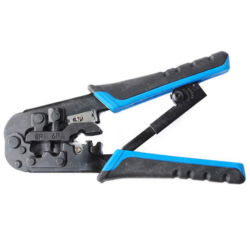
We recommend the Copper Crimping Tool
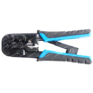
This tool is ergonomically designed for repeated use without causing fatigue or stress to the user. The longer handle designs allow you to apply the pressure from your palm instead of your fingers providing you with better results.
LET’S STRIP
Stripping in our world is intended as the removal of the cabling outer jacket. By doing this step you’re exposing the copper twisted pairs underneath. There are two ways of stripping.
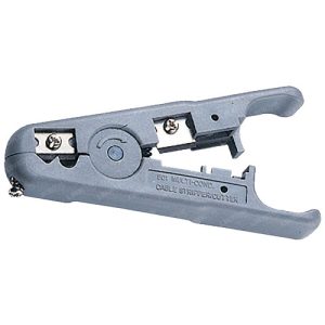
The most common is using this tool to score a ring around the diameter of the cabling jacket, which then allows the jacket to be pulled off. Our model comes with adjustable blades allowing you to control what you’re cutting and avoid any mishaps such as cutting through the twisted pairs, or insulator. Despite how trivial this may seem, even the smallest nick can have an impact on your return loss when you come to test your network.
Experienced installers however tend to keep things simple by not overloading themselves with tools. One of the ways they prefer to strip the jacket is by using their snipping tools to cut about ½ inch off the jacket and then pulling on the rip cord till they have the desired length. Of course, one drawback to this method could be manufactures didn’t include a rip cord and therefore make it harder for themselves.
LET’S TERMINATE
The next step is to terminate the wiring pairs to a Jack. For RJ45 connectors, you should only have about 1 inch with ½ inch that shouldn’t be exceed as untwisted.
High speed installations like CAT6/CAT7 must ensure the same characteristics are kept throughout the circuit, avoiding any signal ‘speed bumps’ along the way. This would have an impact on overall performance of the circuit.
There are two major colour-coding conventions in place for installation. T568-A and T568-B. The recommended colour coding established by TIA is 568-A, however 568-B has long been used by phone systems and therefore become the common popular use. For most commercial LAN installations, choosing either colour-coding convention is fine. Special attentional should be paid in residential buildings though, as 568-A will allow for two-line service whilst 568-B will only allow for one.
Typically, the colour-coding is determined by the patch panel being used, as in most cases it’s hardwired to either 568-A or 568-B, while modular jacks are dual coded meaning, they can be used either way.
When placing the wires down, it’s important not to untwist too much length but also not re-twist too much. By over twisted and exerting the cable you can be affecting the impedance of the cable. You should be careful not to have much too wiring exposed.
Our modular keystone jacks provide a channel area, it’s exactly ½ inch long so if you bring the jacketed cable flush with the back of the connector, it will serve as an accurate guide to avoid exposing an excessive length.
A punch down tool should be used to push/punch the wiring down into the insulation displacement connector (IDC) terminal. By ensuring correct use of the punch-down tool you’re guaranteed a cleaner cut and consistency within your work.
Once all the wiring pairs are terminated, the final step is assembly of the connector body by snapping the cover into place and loading it into the patch panel or wall outlet.
ARE WE DONE?
Your field installer should be the person responsible for carrying out the testing of the terminated circuit. They should be testing for shorts, opens, miss wires, split pairs, shield continuity and more while measuring the length of the cable runs.
It’s down to you to keep proper documentation and cable markings for the installation as aid for any troubleshooting that may arise in the future. Overall, finding the right installer with the right tools and knowledge puts you at a much better position all round.